
1. Definition
- The word connector clearly comes from the word CONNECT. Literally, we can guess the meaning from the word itself. It means it’s a component that connects two devices and transmits electricity, light, and fluids between them.
2. Classification of Connectors
- We can classify connectors into military connectors and civil use connectors by industry applications. We can further classify civil use connectors into vehicle use connectors, telecommunication field connectors, oil extraction field connectors, and medical equipment connectors.
- By shapes, we can classify connectors into circular connectors and rectangular connectors. Different shapes can be suitable for different applications.
- By transmission medium, there are 3 types, electrical connectors, optical connectors, and fluid connectors. Electrical connectors transmit electricity and can serve as power connectors or signal connectors. Optical connectors transmit light. Optical connectors are normally used as signal connectors. Fluid connectors transmit cooling fluid to heating parts, carrying away heat from these parts.
3. Components of Connector
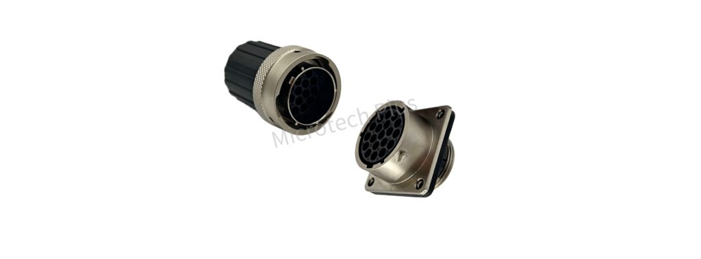
- The connector consists of housing(shell), insulator, contacts(terminals), gasket, backshell, and other accessories.
Connector Explode View
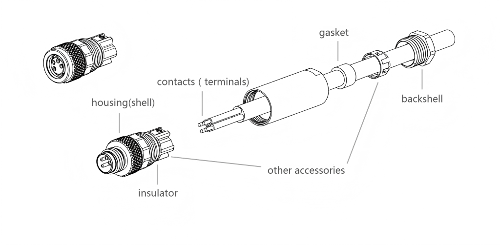
- Housing, which also can be called shell, is the outermost structure of a connector. Housing can protect all components inside connector, and protect user from electric shock during operation. Housing could be made of plastic material or metal material.
- Insulator, which is inside of housing, securely hold the terminals inside the connector. Insulator sets up a barrier between terminals and housing, in case electric leakage happens. Insulator’s material normally is plastic.
- The contacts, also known as terminals, form the key part of a connector. Contacts conduct the electricity or light. The contacts’ electric or optical performance decides the whole connector’s performance. If it’s electric connector, there are 2 types of contact, pin and socket. For electric connector, the contact’s material normally is copper. For optical connector, the contacts normally are optical fiber. There are no contacts inside fluid connectors.
- Gasket, made of rubber normally, it provides waterproofing and dustproofing after the connectors mate or at the cable entry. Gasket structure normally decides the IP degree of a connector.
- Backshell, refers to the component at the rear of a connector, to secure the cable and provide strain relief for internal components. Backshell’s material could be plastic or metal.
- Other accessories, include connector locking mechanism, shielding structure, crimping sleeve etc.
4. Connector’s Key Parameters and Meanings
- Rated Voltage, refers to the maximum voltage at which a connector can safely operate under normal conditions and extreme application conditions(high temperature, high humidity, and high altitude).
Several factors determine the rated voltage, for example, the gap between two contacts, creepage distance, and insulation material types.
- The bigger the gap between 2 contacts, the bigger the rated voltage of the connector.
- The longer the creepage distance, the bigger the rated voltage of a connecor.
- The better the insulation material, the bigger the rated voltage.
- Rated Current (Ambient temperature 30°C): Rated current is the maximum current that a connector can safely and continuously carry under normal operating conditions. A connector’s rated current normally is decided by the contacts’ material, contacts’ cross-sectional area, contact resistance at the crimping part, temperature rise limit, and heat dissipation conditions.
- Talking about the contacts’ material, from highest to lowest electrical conductivity, the order is silver, copper, aluminum, iron.
- The bigger the contact’s cross-sectional area, the higher the rated current.
- The lower the contact resistance at the cable connecting part, the higher the rated current.
- The less strict the temperature rise limit, the higher the rated current.
- The better heat dissipation conditions, the higher the rated current.
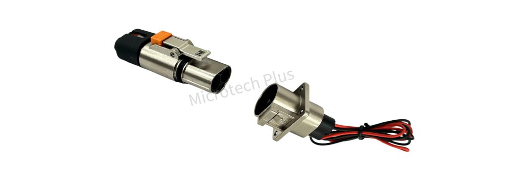
- HVIL Function: The HVIL(High Voltage Interlock Loop) function of connectors is a crucial safety mechanism in high-voltage systems. For example, electric vehicles widely use these kinds of connectors.
- Safety Mechanism and Purpose. It uses an independent low-voltage circuit to monitor the connection status of the high-voltage connector in real time, ensuring that the system can only power on under intact and safe conditions. This effectively prevents electric shock accidents caused by loose or disconnected connections.
- Signal Terminals. The connector incorporates two signal terminals to transmit the aforementioned low-voltage signal.
- Monitoring Principle and BMS Detection.HVIL uses a 12V or 5V low-voltage, low-current circuit to continuously monitor the entire high-voltage system, checking whether all high-voltage connectors are properly and securely mated. The Battery Management System (BMS) determines the integrity of the high-voltage system by detecting the continuity of this circuit.
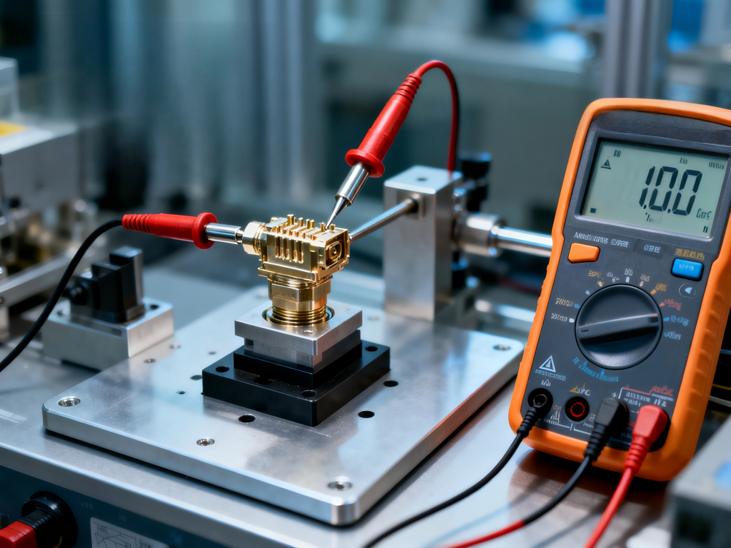
Withstanding Voltage:
The withstanding voltage of a connector refers to the maximum voltage that it can withstand for a specified duration without experiencing insulation breakdown or flashover when subjected to a test voltage higher than its rated voltage.
This test is typically conducted by applying a short-term high voltage. The acceptance criterion is generally whether breakdown or flashover occurs. The result is usually expressed as “pass/fail” or “no breakdown,” and the voltage is commonly measured in volts (V) or kilovolts (kV). A higher withstanding voltage indicates greater electrical insulation strength and a stronger ability to resist transient high-voltage surges.
Factors affecting withstanding voltage include:
Type of insulating material. Manufacturers commonly select plastics and ceramics, which possess inherently high dielectric strength, as insulating materials to ensure high withstanding voltage capability.
Clearance and creepage distances. Contaminants such as dust, salt spray, and oil adhering to the insulator surface can distort the electric field distribution, inducing creepage or breakdown, and greatly degrading withstanding voltage performance.
Environmental temperature, humidity, and air pressure. High temperature, high humidity, or low air pressure environments can significantly reduce the dielectric strength of air or the insulating material, thereby lowering the connector’s actual withstanding voltage capability.
Rate of voltage rise and duration of the applied test voltage. Furthermore, variations in the duration of the applied test voltage or the rate at which the voltage rises may lead to different measured breakdown threshold values.
- Protection Degree:
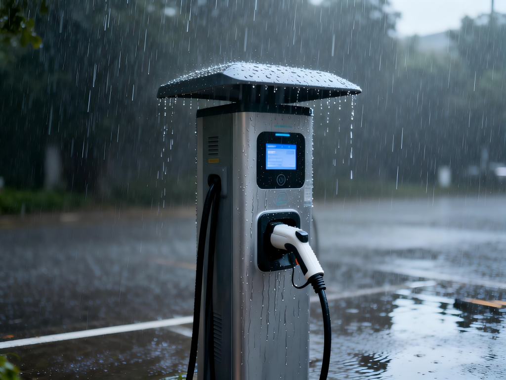
The protection degree (commonly referred to as the IP code, which stands for Ingress Protection) is a standardized indicator of a connector’s ability to guard against the intrusion of foreign solid objects and liquids.
Simply put, it tells you how “dustproof” and “waterproof” a connector is. This is crucial for determining whether a connector is suitable for outdoor, humid, dusty, or harsh industrial environments.
Common protection ratings include IP54, IP65, IP67, IP68, and IP69K.
IP54 offers limited dust protection (allowing a small amount of dust to enter) and protection against splashing water. It is suitable for indoor, dry environments, or places with minimal moisture (e.g., standard office equipment, some household appliances).
IP65 provides complete dust protection and protection against low-pressure water jets. It is suitable for outdoor lighting, industrial equipment, and distribution boxes (capable of withstanding rain).
IP67 provides complete dust protection and can withstand immersion in water up to 1 meter deep for 30 minutes without damage. It is suitable for environments requiring temporary submersion or prolonged exposure to heavy rain (e.g., outdoor sensors, charging stations, diving flashlights).
IP68 provides complete dust protection and allows for continuous submersion in water (the specific depth and duration are specified by the manufacturer, typically ranging from a few meters to tens of meters). It is suitable for underwater cameras, submarine equipment, and underwater robots.
IP69K is a supplementary standard often found in the automotive and food industries (originally DIN 40050-9). It specifically signifies the ability to withstand close-range, high-pressure, high-temperature jet cleaning (80°C, 100 bar).
- Eletromagnetic Shielding:
The electromagnetic shielding of a connector refers to its ability to block or attenuate electromagnetic fields through its structural design (typically a metal or conductive coating). It serves a dual purpose: preventing internal signals from radiating out and interfering with other devices, while also protecting the signal transmission inside from external electromagnetic interference.
Shielding is typically achieved through the following methods:
Metal Housing: For example, an all-metal shell (such as the casing of a circular aviation connector or the top and bottom metal covers of a D-Sub connector).
Conductive Coating: Applying a metallic layer (such as electroless nickel plating) onto a plastic housing. Although the base shell is plastic, the metal layer provides the shielding function.
Shielded Cable Termination: If the cable used has a shield layer (braid or foil), the connector’s shielding shell must be able to securely clamp or solder this shield layer to ensure continuous grounding.
- Physical Life(Mechanical Durability):
The Mechanical Durability (also known as mating cycles) of a connector refers to the number of mating and unmating cycles it can withstand while still ensuring that its electrical performance and mechanical structure remain within specified requirements.
As we know, physical life’s (mechanical durability) unit is Time, for example 100 times, 200 times etc. One issue you should be clear is that each single Time includes 2 actions, mating and unmating.
Physical life answers a core question: “How many times can a user plug and unplug this connector before it is no longer reliable?”
When the number of mating cycles reaches or approaches its rated mechanical durability, the following issues may occur:
Increased Contact Resistance: After the plating wears away, the base metal (typically a copper alloy) is exposed to air and may oxidize. This leads to higher contact resistance, which can cause overheating or signal degradation.
Changes in Mating/Unmating Force: The connector may become too loose or too tight, resulting in an abnormal feel during operation.
Physical Damage: Plastic latches may break, the housing can wear down, or contacts (pins/sockets) may become bent or misaligned.
5. How to Choose A Connector?
- Firstly, you need to decide the connector’s application field. The requirements for connectors vary dramatically across different applications.
For example, connectors used in the consumer electronics sector are typically characterized by miniaturization, multi-function integration, low cost, and high-frequency/high-speed performance.
- Miniaturization: To fit into products like smartphones and wearables, consumer connectors must be ultra-thin (e.g., as low as 2.5mm in height) and compact (e.g., with a 0.5mm pitch). These connectors are highly integrated.
- Multi-function Integration: A single universal interface, such as USB Type-C, often integrates high-speed data transmission, charging, and video signal capabilities.
- Low Cost: Due to the enormous production volumes, cost control is critical. As a result, designers design the structure of many connectors to be very simple.
Another example is connectors used in automotive electronics. Their core characteristics are extremely stringent standards, resistance to high and low temperatures, vibration resistance, and high-voltage capability.
- Stringent Standards: They must comply with industry-wide specifications, such as the U.S. automotive standard SAE USCAR-2. This standard details the performance requirements and test methods for connectors regarding vibration, thermal shock, and salt spray corrosion.
- Environmental Robustness (Temperature & Chemical Resistance): The connectors must withstand extreme temperature fluctuations, oil contamination, and continuous vibration within the engine compartment, ensuring that connections never loosen.
- Platform Trend (High-Voltage Trend): With the rise of new energy vehicles, connectors are facing new challenges posed by high-voltage platforms (e.g., evolving from 60V to 800V or even higher). This places greater demands on insulation and safety.
- Secondly, you need decide the voltage and current value.
The operating voltage of a connector must align with the system voltage of the equipment; a mismatch will render the connector unusable. Therefore, confirming the voltage requirement is the essential first step.
Next, determine the current requirement. The current level directly determines the physical size (mainly the cross-sectional thickness) of the connector’s contacts and the appropriate wire gauge. The general correlation between wire size and current-carrying capacity is shown below:
| Wire Gauge (mm2) | Wire Gauge (awg) | Loading Current(A) |
| 2.5 | 13 | 20 |
| 4 | 11 | 25 |
| 6 | 10-9 | 40 |
| 10 | 7 | 60 |
| 16 | 5 | 80 |
| 25 | 3 | 120 |
| 35 | 2 | 150-200 |
| 50 | 1/0 | 200-250 |
| 70 | 2/0 | 250-300 |
| 95 | 3/0-4/0 | 300-350 |
| 120 | – | 350-400 |
| 135 | – | 400-450 |
| 150 | – | 450-500 |
- Thirdly, you need to decide the requested connector’s core number and protection degree(IP Degree, which means Ingress Protection Degree)
- Connectors are designed with different pole configurations—such as 1-pole, 2-pole, 3-pole, and multi-pole—primarily to meet the diverse requirements of various applications in terms of circuit count, functionality, and spatial layout.
- Engineers must evaluate the Ingress Protection (IP) rating based on the actual application environment and installation location. The IP rating primarily addresses the ability to resist the ingress of solid objects (such as dust) and liquids (such as water).
For example, connectors used in consumer electronics typically require IP54 or IP67 ratings. These connectors generally need to be splash-proof, and some require protection against temporary immersion in water.
Automotive connectors, on the other hand, commonly require IP67 or IP69K ratings. These connectors must withstand immersion in water and resist high-temperature, high-pressure water jets.
One Response
Nice!